How Metasurface Lenticular Lenses Enable 2D–3D Switchable Displays

Why a thin, switchable 2D–3D display matters
Consumers and businesses increasingly want display hardware that can do double duty: high‑resolution 2D imagery for productivity and crisp 3D visuals for immersive experiences. Traditional approaches use bulky optics or permanently segmented pixels, which trade image quality or form factor. A metasurface lenticular lens (MLL) changes that calculus by combining ultrathin optics with electrically controlled switching, enabling a single panel to act as either a conventional 2D display or a light‑field 3D display with parallax cues.
This technology brings three practical advantages: a much thinner optical stack (the MLL itself can be ~1.2 mm thick), a large field of view (the reported prototype achieves around 100°), and scalability for reasonably large active areas (up to 25 cm² demonstrated). That combination is attractive for everything from smartphones and tablets to retail signage and heads‑up displays.
What a metasurface lenticular lens is, in plain terms
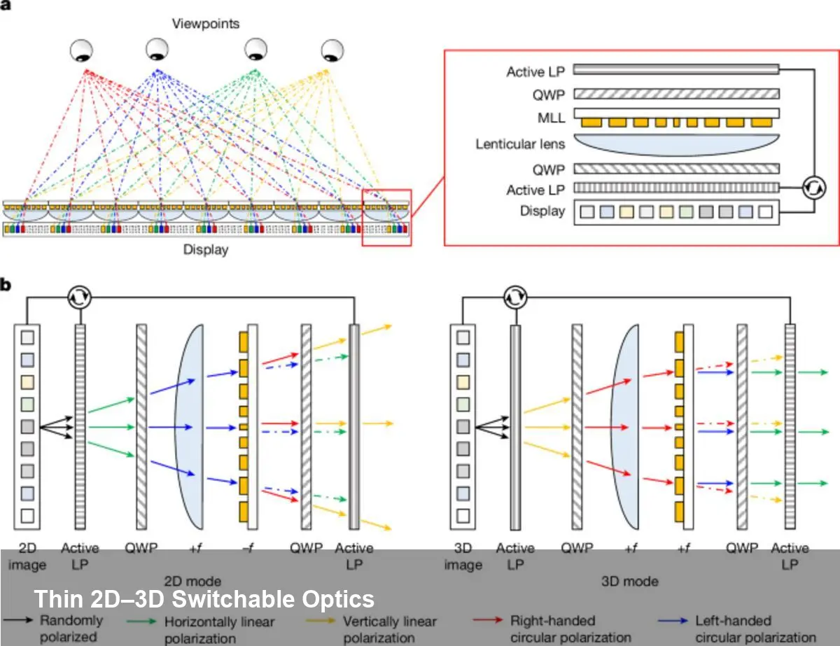
Metasurfaces are engineered sheets of nanostructures that alter light’s phase, amplitude, or polarization at subwavelength scales. A lenticular lens is an array of cylindrical microlenses that directs different views to different eye positions — it’s the classic approach behind parallax 3D prints. An MLL merges those ideas: the lensing behavior is encoded in a nanoscale metasurface that can be designed to change how it focuses light depending on the incoming polarization.
In practice, the panel stack pairs the MLL with a thin polarization control layer (often an electrically driven liquid crystal element). When the polarization state is one way, the metasurface behaves as a lenticular array and routes multiple angular views to form a light field — producing depth and motion parallax. When the polarization is switched, the metasurface presents a normal optical response so the display behaves like a conventional high‑resolution 2D screen.
Concrete scenarios where this is immediately useful
- Mobile products: A smartphone could present standard 2D UI for email or reading, then switch to 3D when viewing interactive maps, AR overlays, or product demos without adding mechanical parts. The thinness (≈1.2 mm) preserves modern industrial design.
- Retail and kiosks: Digital signage can alternate between crisp promotional images and immersive 3D product views to increase dwell time and conversion in stores; a 25 cm² active MLL prototype shows this is plausible for real‑world-sized panels.
- Automotive/AV heads‑up displays: Wide FOV (~100°) lets designers create realistic depth cues for navigation or driver assistance overlays while retaining a standard 2D mode for menu systems.
- Medical and industrial visualization: Surgeons and engineers could toggle between flat 2D content for paperwork and volumetric 3D renderings for planning or inspection.
For developers and content creators: what changes in workflow
Creating content for a switchable 2D–3D panel is not just about adding depth maps. Expect at least two parallel pipelines:
- 2D pipeline: traditional high‑resolution raster or vector assets optimized for sharpness and color. In 2D mode the display should retain native pixel fidelity.
- Light‑field/3D pipeline: either capture a light field (multi‑camera arrays or plenoptic capture) or synthesize multiple views from 3D models/point clouds. Important metrics are angular resolution (views per degree), parallax budget (how much apparent depth vs. crosstalk), and brightness loss through the optical stack.
Practical tips:
- Add an application toggle that switches the polarization control layer and syncs content. Rapid switching is possible with thin LC layers driven by modest voltages.
- Calibrate view‑mapping to each panel during manufacturing — misalignment between the OLED subpixels and the MLL’s phase map causes ghosting.
- Use eye‑position detection (e.g., stereo cameras or eye tracking) to adapt view allocation and reduce perceptual artifacts and bandwidth requirements.
Hardware and integration considerations
The MLL’s high numerical aperture is what enables wide FOV while keeping the device thin, but it also tightens alignment tolerances. The metasurface pattern is highly sensitive to nanometer‑scale placement relative to the display pixels. That implies manufacturing complexity: either precise assembly in factory lines, or designing mechanical tolerances into the optical stack.
There are other tradeoffs to budget for:
- Brightness: Light‑field routing distributes light across multiple views, so peak luminance per view is lower than full‑screen 2D. Designers must compensate via display brightness or dynamic mode switching.
- Color fidelity and crosstalk: Achieving full‑colour performance with metasurfaces across visible wavelengths requires broadband design strategies, which are advancing but still more complex than simple refractive optics.
- Power: The switching mechanism (usually an electrically driven polarization layer) consumes power, but compared to mechanized optics it’s efficient and quick.
Pros, cons, and realistic limits right now
Pros:
- Extremely thin optical profile (~1.2 mm) suitable for modern devices.
- Wide viewing angle (~100°) enabling natural parallax cues across a large area.
- Demonstrated scalability to practical panel size (active area ≈25 cm²).
Cons/limits:
- Manufacturing and assembly precision are demanding; cost will depend on how metasurface patterning scales (nanoimprint vs. lithography).
- Content creation is more demanding for high‑quality 3D output; many apps will require new tooling or conversion pipelines.
- Brightness and angular resolution tradeoffs mean not every application benefits from always‑on 3D mode.
Strategic implications for startups and product teams
Startups building AR devices or premium mobile hardware should view MLL‑based displays as a near‑term path to blending 2D and 3D without heavy optics. The quickest product wins will be features that exploit 3D as a mode rather than a constant — for example, contextual 3D previews, navigation overlays, or product demos that users opt into.
Product teams should prioritize the content and UX integration: make switching instant and predictable, provide clear affordances, and optimize the 3D pipeline for short, high‑impact interactions rather than trying to port full traditional 3D desktop workflows directly.
Where this tech is headed
- Eye‑tracking + dynamic view synthesis: Steering light‑field views to tracked eye positions can boost perceived resolution and reduce wasted light.
- Per‑pixel dynamic optics: Advances in metasurface fabrication could enable localized focal control at pixel scales, letting displays mix 2D and 3D content across the same screen region.
- Manufacturing scale‑up: Nanoimprint lithography and roll‑to‑roll metasurface fabrication are plausible paths to reduce cost and make larger panels economically viable.
If you’re evaluating this approach, prototype early with a small active area (the published demos used about 25 cm²) to validate UX and content flows. From there, consider where 3D adds measurable value for users — that will determine whether the additional engineering and manufacturing complexity pays off.